Chip mess and suction issues
Moderators: piaptk, tragwag, Steve E., Aussie0zborn
Chip mess and suction issues
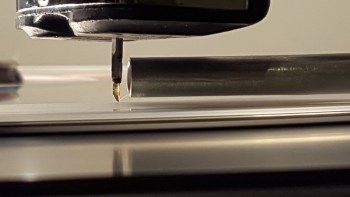
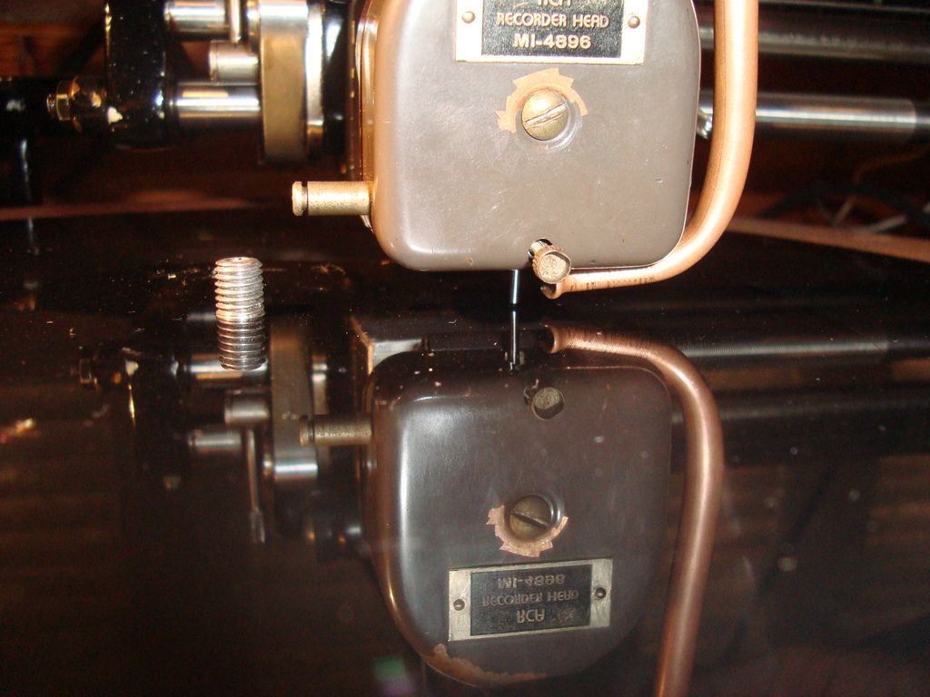
The result of my latest attempt at retrofitting the RCA head adaptor with a chip suction tube, has resulted in a suction tube chock full of chip. As in, packed full.
The hose upstream is clean. Rubber vacuum hose, that is. Not much is ending up in the chip jar, its all sticking in the first part of the tube. This happens just as much with lacquer as it does with PVC.
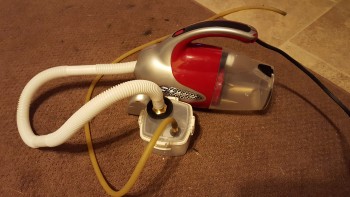
I am assuming that the problem is the vacuum pump. At the moment, it is a pretty strong vacuum cleaner, but strong as in airflow, airflow alone is not enough to properly draw the chip. What is needed is pressure, or the opposite of it, which is vacuum. When using a tiny tube to collect the chip, airflow is being restricted anyway. The problem with vacuum cleaners is that although they can provide a high volume suction, they do not have real vacuum capacity. Even if you restrict the airflow the vacuum does not see a significant increase. In a real vacuum pump, the idea is that reducing airflow increases the vacuum. Unless there is a safety system in place, a significant restriction in airflow would result in a significant increase in vacuum, which is what we need to really be able to pull this mess up. I have also tried an aquarium pump, which was a bit of a joke. I am now waiting for a real vacuum pump to arrive and will be trying the same system with it.
The vacuum cleaner was only able to produce - 160mbar of vacuum. I am hoping to do much better with the vacuum pump.
Anyone having any other pointers or ideas on this subject please feel free to contribute.
~~~ Precision Mechanical Engineering, Analog Disk Mastering ~~~
Agnew Analog Reference Instruments: http://www.agnewanalog.com
Re: Chip mess and suction issues
Is the chip hanging in the suction tube or the metal tube? (Your photo looks like a piece of copper tubing.) It's possible you have a metal burr somewhere at either end of the copper tube, which would cause the chip to hang. I have made custom suction tubes out of copper and always sand the ends - inside and out - for quite a while with fine emery cloth to make sure there are no burrs or other obstructions. Another possibility is if you're using latex tubing from the metal part to the chip jar, fresh latex needs a dose of talcum powder before starting sucking chip. The fresh latex is "sticky" and can cause hangups. Hope this helps.
Re: Chip mess and suction issues
What a coincidence, I just finished my system and it seems to be working fairly well so far cutting Laserdiscs. Smaller chip than what I think comes from PVC or lacquer cutting, more of a fine cotton candy. I haven't perfected the process yet.
I tried the aquarium pump as well, no go. I also tried a 12v DC pump made for science projects and such, also a no go. I ended up going with a handheld vacuum cleaner, a Dirt Devil Classic with a 7 Amp motor. I did some hacking to hook it up to a small chip jar made out of an air tight cracker container. My suction side has a 3/4" connector and the chip side is reduced at 5/8" inch. I use some 3/8" ID latex to a bent aluminum tube. It's called Pilot Burner Tubing, comes in a 5' roll, and is really easy to bend. Picture at the end.
Without pictures of your tube and system, my first thought is what is mentioned above about something catching chip in your tube or at the transition to your from metal to rubber tubing. Are you using latex or a harder rubber like fuel line? Also, is there a bend in your metal tube and if so how tight is it? Then there's the size of your connectors/hoses. I found that the larger the better, especially coming from the vacuum to the chip jar but that also size of the jar seems to make a difference. A larger jar for my hose sizes put too much strain on the vacuum when using a small hose to the metal tube.
Re: Chip mess and suction issues
I should definitely check again for burrs. I deburred it but could be that I missed something. The problem is only on the suction nozzle. It is this piece of 1/4" copper tube with a bend in it but with enough space for large size chip. It is flattened at the end so it can fit under the cutter head. In the top end of it I have connected a rubber vacuum pipe. It is similar to a fuel line but would probably not withstand contact with fuel for very long. The rubber pipe is fairly short and is connected to another piece of 1/4" copper tube that has a few bends and ends up very near the chip jar. Then there is another short piece of the rubber vacuum hose connecting it to the chip jar. The chip jar is fairly large. On the other side there is a 3/4" rubber water hose connecting it to the vacuum cleaner. The vacuum hose is the kind of stuff they normally use in cars for the vacuum connection such as these going to the break servo. The copper tube is thin wall low pressure pipe, commonly used for gas lines and fuel lines. When I change over to a proper vacuum pump the hose between the chip jar and the pump will most likely be much smaller to fit directly to the pump inlet.
There is chip ending up in the jar, quiet a bit of it, and there is no chip sticking anywhere else apart from the very short length of the pipe on the cutter head. The funny thing is that it sticks on the rubber hose end, and not on the open end, although the real problem is that there really isn't much suction power on this thing. I tried different powdery stuff and it needs to be pretty much touching it to do anything.
~~~ Precision Mechanical Engineering, Analog Disk Mastering ~~~
Agnew Analog Reference Instruments: http://www.agnewanalog.com
Re: Chip mess and suction issues
I'm slightly confused, where is your loss of suction? Is the vacuum itself not very powerful or is it after all the tubing? I wonder if you are reducing air movement with the bends just prior to the chip jar. Possibly those bends are reducing flow to the point that some of the chip is getting stuck at the transition from your first tube to your hose. For mine I have the piece of aluminum mounted to the lathe, then the latex straight into the chip jar using a barbed gas connection. I'll post some pics this evening. I had a hell of a time getting just the right sizes, always having one stage going into a larger one back to the vacuum cleaner.
- EmAtChapterV
- Posts: 244
- Joined: Sun Jan 06, 2013 6:49 pm
- Location: Vancouver, BC
Re: Chip mess and suction issues
I second what the others have said about burrs in the copper tubing. I've had the same problem, even with the largest copper tubing and latex hoses that would physically fit, and sanding them within an inch of their life. Burrs and static buildup were the number one cause of failed cuts for me.
An important thing is to make sure the chip doesn't have to turn a corner to get into the mouth of the tubing. If it rubs against the edges, that's one more way for static to build up and cause a clog.
Re: Chip mess and suction issues
Nice pictures! My setup is fairly similar with the main difference that I used a very short initial copper tube, then rubber hose, and then copper tube again. The total length of copper tube is slightly more than yours, with much shorter rubber hose.
The reason for this was to minimise any effect of weight and resistance of the rubber hose on the suspension, since the copper tube moves together with the cutter head.
The large hose on the other side of the chip jar is similar but different material.
I think the biggest problem is that the vacuum cleaner is either unable to produce enough of a vacuum or has some kind of safety device in place so the pump does not get over worked in case of restriction. Even when I physically plug the vacuum cleaner hose with a palm of my hand, the motor does not slow down much and the vacuum against my palm is not what I would call strong. With a real vacuum pump I think it would be fairly dangerous to do that. I have a vacuum gauge on the chip jar to be able to use some kind of visual indication to put some numbers to this. No matter what I do, the vacuum does not register over -160mbar. This is -1.8psi. This does not seem to be enough to reliably pull chip away from the needle. I think I would need a pump that would be easily capable of generating a vacuum of -500mbar or -7.2 psi in this system.
Then I can play with the variac and find appropriate values of vacuum for each material.
If anyone has any numbers, either of the vacuum generated in the system or the volume rating/hp rating of your vacuum pump, please feel free to contribute.
The only other difference is that due to the geometry of my cutter head and suspension, I had to attach the copper tube on the side of the head and not behind it. Similar to the Westrex 3D suction tube.
This is a picture of my old suction tube which was a bit short and on which I had flared the entrance. I thought that a flared entrance would make sense but I am not really sure about it, after trying it out. It seems like a non flared entrance works best for suction. This is also probably because I am using 1/4" copper tube. I might try 3/16" when I receive the real vacuum pump. This one might be better off flared due to its small internal diameter. 3/16" would also probably fit behind the cutter head, whereas 1/4" only fits on the side.
The old RCA lathes and heads had a suction tube mounted in front of the cutter head, which seems a bit odd. Obviously, this might work with a cold stylus but I wouldn't want to try it with a hot stylus.
~~~ Precision Mechanical Engineering, Analog Disk Mastering ~~~
Agnew Analog Reference Instruments: http://www.agnewanalog.com
Re: Chip mess and suction issues
If you cut the copper tube with a standard tubing cutter and used the deburring blade on it, it's not smooth enough. You HAVE to use emery cloth and literally polish the cut ends absolutely smooth. A quick deburring with the tool is fine for water pipes, but not for suction pipes for disc thread. It will hang up and clog the tube.
Re: Chip mess and suction issues
I did not use emery cloth but I used a series of brushes on a dremel to polish both ends of all copper pipes I used. Started with steel wire, moved on to copper wire, and then plastic polishing brush. I will check gain though, perhaps I could get it even smoother.
~~~ Precision Mechanical Engineering, Analog Disk Mastering ~~~
Agnew Analog Reference Instruments: http://www.agnewanalog.com
Re: Chip mess and suction issues
I think working on your current tube to polish it while you're waiting for your new vacuum pump to arrive is the best bet. Then you can test it's capacity with your current design. Is it at all possible to mount the tube directly behind the cutting stylus? I was looking at some pictures of the 199 and it looks rather complicated with the way the carriage is designed. I guess if it doesn't work out you can do what they did back in the day, instead of using suction you blow air across the stylus to push the chip toward the center of the record to wind on the spindle. Looks like your tube is already perfectly positioned for it.
- smithadamm
- Posts: 63
- Joined: Tue Jun 03, 2014 1:32 pm
- Location: Austin TX
Re: Chip mess and suction issues
You can check for major burrs by running a piece of dental floss through the copper tube and kind of "flossing" around the inside surface to see if it catches. This will mostly only help if there is a pretty major burr.
Re: Chip mess and suction issues
As most pointers make sure it is really clean internally
I suggest that you Flatten the mouth of the tube to a delta shape first like a fish tail
Make sure that it is very smooth
Mount a short piece of the new shape on the head itself than use a tube of greater diameter to sit over the smaller diameter tube but not touching it so you will have a tube within a tube it does not need to be inserted any more than around the 5-8 mm into the outer tube
So if you have a 6 mm suction tube the diameter of the external tube should be about 12 mm that's where the vacuum cleaner tube should be fixed
You will get a Venturi effect the vacuum cleaner at around the 60% power will suck any chip
Standard on any Neumann lathe and you can try it out by using what you already have
By the way the suction tube on a vms is around the 3-4 mm diameter with a 90 degree bend so it sucks from the side of the cutting stylus it works with a simple domestic vacuum cleaner
Alternatively find a used vacuum pump from a printing press and use it for the source of negative pressure
Good luck with it
Chris
Re: Chip mess and suction issues
That sounds interesting. Would you be able to draw some schematics ?mossboss wrote:You will get a Venturi effect the vacuum cleaner at around the 60% power will suck any chip
Michaela
Re: Chip mess and suction issues
Photos are better than words. Ha
You do not have the required permissions to view the files attached to this post.
Chris
Re: Chip mess and suction issues
Interesting. I looked up the Venturi effect last night and most of what I saw was a single tube with a narrowing and then slight expansion. Just to affirm what I see in the pictures - the suction tube attached to the head that makes the 90% turn to end up right behind the stylus is the tube seen in the lower portion of the picture (pictures show rotated counterclockwise 90% on my computer) and then the second larger tube is attached to the lathe. The small tube is inserted into the large one 5-8mm. Currently my chip collection is working but only for very small chip. I'll have to keep this in mind if something goes awry. Implementing the dual tubes would be an interesting process given my Presto uses a pivot mechanism with weights and a spring. Great information, thanks!
Re: Chip mess and suction issues
That's a really interesting idea! So, the small tube is only attached to the cutter head? Does it move freely within the larger tube? Thanks for that Chris.
Rsimms3, the venturi effect does not have to do with the single tube but rather with an orifice on the side of the tube at the narrowing point. This is the most common implementation of it although it can also be implemented in other ways. The idea is that airflow through the main tube creates a vacuum in the venturi, which is the small orifice. This is essentially how carburettors suck in fuel and mix it with air. The air comes in through the big hole by the suction of the pistons of an internal combustion engine and this creates a strong enough vacuum to pull fuel in. Any change in airflow also changes the amount of fuel so you maintain the correct stoichiometric ratio of air to fuel.
I will definitely be trying this out.
To get the suction tube behind the stylus on my system would require two bends. A bit behind the stylus there is a part of the head protruding downwards blocking access from behind. The suspension, mounting adapter and carriage would have no problem with a tube coming from the back. With a different cutter head it would work, but with the one I am using at the moment, it's tough.
As for blowing air, this would be easy although I never tried it. I'll have to try this out one day just for the experience, but I can imagine it would be rather messy. I already have compressed air here for other stuff, so it wouldn't be that hard.
It seems that most modern professional systems if not all, had the suction tube placed on the side of the stylus. Neumann heads did it this way, Westrex heads as well, Flos Caruso I think does the same, and Todds Bladerunner, too. So I guess, this is unlikely to be my problem.
We shall see...
~~~ Precision Mechanical Engineering, Analog Disk Mastering ~~~
Agnew Analog Reference Instruments: http://www.agnewanalog.com
Re: Chip mess and suction issues
I saw a lot of diagrams such as the one below. I also saw some like you mentioned with the smaller tube intersecting at the narrowing. Seems to be implemented more with relation to fluids like your carburetor example. Definitely an interesting science lesson.
Re: Chip mess and suction issues
Thanks. That makes it easier to understand.mossboss wrote:Photos are better than words. Ha
mm.
Re: Chip mess and suction issues
Fluid and air behave in a very similar fashion so a Venturi effect will have the same effect on both
It's been known since it was first proposed in the 16th century it's no news
By the way every aircraft out there has a pitot tube which is the means of reading air speed which is the only way that a pilot can tell his actual rate of travel. It is based on the very same principle
Best
It's been known since it was first proposed in the 16th century it's no news
By the way every aircraft out there has a pitot tube which is the means of reading air speed which is the only way that a pilot can tell his actual rate of travel. It is based on the very same principle
Best
Chris