
Working up a cutting chain, and wondering is someone would be prepared to do a little schematic review for me?
This one is all analog, mostly because I spend my days fucking with digital audio for work and the Z plane is kind of boring at this point.
First up, we have a stereo inverse RIAA, balanced in and out, with low and high frequency 'shelving' eq as an option that returns to zero gain out of band (Idea from Doug Selfs crossover book), relay switched for removing the 75us zero and a pair of relays that switch in more capacitance to double the time constants for half speed cutting. Both the half speed and the equalisers are stuffing options, and can be omitted relatively easily if either the machine cannot do half speed or the stage is being used in something like a preview chain where you don't want the EQ.
If someone could kindly take a look and confirm that the -10dB before the 75us zero is sufficient to keep the thing from clipping with sane input levels (I think it is ok up to about +8dBu or so at 20k as long as you don't go too nuts with the HF shelf), so +4dBu for 5cm/s with 14dB of headroom seems sane given there is a HF velocity/acceleration limiter preceding this thing? I could really use someone having a look at the gain structure for sanity.
Just for shits and giggles all the in chain caps are ceramic (C0G), and I have gone servo rather then electrolytic for DC block, personally I got no problem with electrolytics if carefully chosen, but enough folks do that you may as well play the game.
And yea, I know I have somehow ended up with 16V caps on a 17V rail, fixing it.....
Gerbers and BOM once I am happy with them and have built and tested at least one card.
Any chance of some schematic review?
Moderators: piaptk, tragwag, Steve E., Aussie0zborn
Any chance of some schematic review?
You do not have the required permissions to view the files attached to this post.
-
dubcutter89

- Posts: 359
- Joined: Thu Oct 19, 2006 6:30 am
- Location: between the grooves..
Re: Any chance of some schematic review?
Hey!
Had a quick look and it seems to do the things you've described.
- Input (That) -6dB (but I have not seen a defined input load resistance nor a bias current path!)
- 50kHz filter and servo should have unity gain
- Low EQ, I don't know because the topology is a little new to me so I cannot give detail answer on this (sorry don't have hours available for reviewing this thing just for fun). But wiper middle position should be unity gain and inverting
- 318, 3180us passive should be fine and the gain @ 1kHz is -10dB with an inverted output
- 75us fine as well
- High EQ, same as above...
- with the final inverting output stage (That) and the previous inverting stages you should have correct phase from In to Out (4 times inverting total (?))
- with the -6dB Input and +6dB Output Chips you'll end up around -10dB from the RIAA stage
>> Just for shits and giggles all the in chain caps are ceramic (C0G)
Do you mean ceramics for audio? That's new to me and I normally use film in my designs...why ceramics?
Also I don't see the usual 100n bypass on the rails next to the chips, just a big 10u electrolytic...why?
IMHO your gain staging is quite over the top...better safe than sorry
A simple passive pad (or pot) in front of all will take care of it and adds a level adjustement that can be handy for setup....just my primitive design...
Example: A power amp with 40V rail (around 100W rms into 8Ohm) and typically 26dB gain needs 2V input signal for full modulation (or start of clipping). All below the 17V rails of the preamp..
With -10dB gain in your pre you're around 0,7V (approx 0dBu) on the input for max power to coils...
Lukas
Wanted: ANYTHING ORTOFON related to cutting...thx
Re: Any chance of some schematic review?
Thanks Lukas, appreciate it, there are things you just cannot see looking at your own circuits.
Not all ceramics are created equal....
The ceramics in the audio path are all C0G, a class I dielectric that is (Finally) available in sane values for audio doings. It is essentially blameless, and much less of a pain in an almost all SMT design then PP or PPS film would be (You CAN get PPS film SMT caps, but process heat becomes really critical). High value C0G is why nobody much cares that polystyrene film caps are not really available any more. The reason everyone looks askance at ceramics is the class 2 dielectrics (X5R.X7R,Y5V and friends) which are suited only to power decoupling.
The 10uF decouplers are actually 1206 X7R ceramics, not electrolytic caps which do just fine at high frequency (In the audio sense). In fact the only electrolytic caps in this thing are in the power supply or the common mode loop of those THAT chips.
The THAT input stage chips handle the bias currents internally, so do not need to provide a DC bias path to the inputs (and indeed doing so would ruin the common mode impedance), and the DM impedance is 48k which is not insane, might be worth adding a resistor to make this 10k, but I don't see that going a little higher hurts anything.
Those equalisers are at heart just a buffered first order RC scaled to give +-10dB and fed into the non inverting input of the control amplifier, everything else is doings to avoid pot wiper noise or dc on switches causing clicks.
I have never understood why power amps typically clip at a volt of so, when basically everything can swing at least 10V, but there is going to be a feedback loop compensation board between this and my power stage which has the drive and feedback controls, so I am not too worried about it.
-
dubcutter89
- Posts: 359
- Joined: Thu Oct 19, 2006 6:30 am
- Location: between the grooves..
Re: Any chance of some schematic review?
Sounds good - Keep us updated when finished!
Wanted: ANYTHING ORTOFON related to cutting...thx
Re: Any chance of some schematic review?
Well it was a nice idea, but the controls don't quite fit across the front of a 100mm eurocard! I always forget just how little space you have on the front of a card.
Decisions, decisions....
Decisions, decisions....
-
dubcutter89
- Posts: 359
- Joined: Thu Oct 19, 2006 6:30 am
- Location: between the grooves..
Re: Any chance of some schematic review?
Hmm, I made a stereo preamp with the same stuff minus EQ but with feedback control and didn't had big problem with eurocard space...
maybe go for dual mono for that extra mojo
maybe go for dual mono for that extra mojo
Wanted: ANYTHING ORTOFON related to cutting...thx
Re: Any chance of some schematic review?
I have slightly reworked it, continuously variable corner frequencies and only one switch, basically a slightly re-scaled version of D.Selfs preamp EQ from Linear Audio (His corner frequencies were fine for hifi, but wrong for fixing spring back), which pots being smaller then those Grayhill switches does now fit in the card cage.
Bit of a pity as I don't actually much like using pots for this sort of thing, difficult to repeatably set and inter channel matching is iffy (You also end up with more buffers in the doings then my set of Hornby, pot wipers not being good at current if you want good linearity and low noise).
I moved the HF EQ to before the IRIAA stage so it could share the control amp with the LF EQ, hurts noise at high frequency a bit, but it is Vinyl for fucks sake, alleged to manage all of 80dB dynamic range (And I do NOT believe that!), I would have to really screw up for the electronics noise floor to become dominant.
The issue was never the components, even using 1206 everywhere it fits on the board easily, I went for 100 * 220 rather then 160 as it costs almost nothing extra and makes repurposing an old DA sub rack that I have easier.
I considered mono cards, and actually have a design for a program eq/feedback card, but hate the thought of trying to set both LF and HF equalisers the same with any sort of reliability, besides if you do the preview thing it amounts to a LOT of cards, and there is little point with modern components.
I expect I will finish the layout this weekend and probably submit the Gerbers to China next weekend (Always wait a week then re check), so I should have the basics on the Prism to make some measurements mid October all being well.
-
Kiss the Groove
- Posts: 24
- Joined: Tue Jan 31, 2012 11:42 am
Re: Any chance of some schematic review?
I haven't tuned into the Trolls in a while, so I know I'm late to the game here, but I thought I'd mention that D21 seems to be backwards in the clip detector.
I'm puzzled by the protection diode arrangements on the Input Stage sheet (D1-3, D6-10). As drawn, they limit the voltages at the +/- inputs of U2A and U4A to about +/- 29V. Was that your intent?
Cheers -- KtG
I'm puzzled by the protection diode arrangements on the Input Stage sheet (D1-3, D6-10). As drawn, they limit the voltages at the +/- inputs of U2A and U4A to about +/- 29V. Was that your intent?
Cheers -- KtG
Re: Any chance of some schematic review?
Yea the ZD in the clip detector was backwards, spotted that when I got the boards back (Always the way)!
The input clamp diodes allow for the fact that the line receiver has a common mode range that extends outside its supply rails (It has -6dB of gain), and are there purely as protection from a wiring cockup elsewhere in the system, I seldom expect them to actually have to conduct, but all external IO should have protection.
I have actually subsequently split the thing up as an IRIAA board and separate EQ card so that it fits in a 100*160mm rather then 220mm card because that makes a pile of old sub racks I have usable. 1206 components make hand assembly easy, but don't half eat space, especially if you want to have component designators on the board.
Also had to change the pots to use the Vishay/Spectrol pin spacing, grumble, parts availability problems with conductive plastic pots.
I also re jigged the switching in the IRIAA section to get me a gain reduction of 6dB when running in half speed mode (Which keeps groove amplitude correct) and save a few caps.
Thanks for taking a look.
-
Kiss the Groove
- Posts: 24
- Joined: Tue Jan 31, 2012 11:42 am
Re: Any chance of some schematic review?
Thanks for explaining the input protection. I wasn't familiar with the THAT1200 series, and you motivated me to pull up the data sheet. That's a fairly impressive part, especially for the cost.
It sounds like you're making good progress. I look forward to your future notes.
Cheers -- KtG
It sounds like you're making good progress. I look forward to your future notes.
Cheers -- KtG
Re: Any chance of some schematic review?
Well the first try was 'close, but no cigar', I went for LH1518AAB photomos switches instead of relays (Because relays without whetting current are nearly always trouble long term), and it NEARLY worked. The photomos is beautifully linear as a switch, far superior to jfets in that respect, but does have some shunt cap and as it turns out an annoying amount of series resistance (35pF and 20 ohms or so for this one).
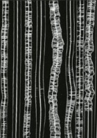
The curves are full and half speed (with a 6dB difference at 1kHz to make the grove amplitudes work out) with the 75(full speed) or 150us (half speed) equaliser in or out. Everything is 6dB hotter then it will be because THAT1206 in SOIC are basically like hens teeth at the moment, Mouser are promising me some in February (Grumble, been a shit year for parts sourcing)!
The problem is that there is a bit of a stray offset between the gains of the 75 and 150us poles and again the same thing for the low frequency ones, the middle bits of the diagonal parts of the curves should overlay and they do not. Pretty sure this is a problem with the on resistance of the photomos stuff, and can probably be fixed by reorganising the switching a bit, who knew that 20 odd ohms of stray resistance could cause that much offset (Actually, it becomes obvious when you think it thru and do the sums).
I suspect that in reality cutting with this would work just fine, but I am sufficiently OCD to want to try to get it right.
The semi parametric equaliser for fixing up springback does however work as intended, apart from running bloody hot (10mA supply into a soic8 opamp is north of 300mW at +-17V), that adds up real quick!
Currently trying to simplify that, as at present it has more buffers then Euston station, and I cannot help but feel it could be rather simpler.
That bit looks like this : The board set LEDs are two power rails, Half speed mode engaged (Controlled by a signal on the backplane connector) and 75uS disabled (Switch on the card, also pin on backplane connector as this activates power limiting mode and changes the operation of the RIAA stage on the monitor card (to follow).
Upper PCB has HF and LF gain controls, EQ in/out switch and HF/LF corner frequency controls. Pots are set back as there are intended to be a screwdriver adjustment rather then a causal thing.
Onward to the next version, also the monitor board, HF limiter board, feedback board, backplane, test tone generator, power supply board, motor control board, power amplifier board sets (Amplifier, Power supply, circuit breaker). Yea, big project, just the way I like 'em.
You do not have the required permissions to view the files attached to this post.

Re: Any chance of some schematic review?
hi guys! I found a video on the internet! Do you have any information on how to assemble the machine?
https://www.youtube.com/watch?v=JmUC09cAq7U&t=232s
https://www.youtube.com/watch?v=JmUC09cAq7U&t=232s