Mysterium Lathe - Restoration Project (Picture Heavy)

This is where record cutters raise questions about cutting, and trade wisdom and experiment results. We love Scully, Neumann, Presto, & Rek-O-Kut lathes and Wilcox-Gay Recordios (among others). We are excited by the various modern pro and semi-pro systems, too, in production and development. We use strange, extinct disc-based dictation machines. And other stuff, too.

Moderators: piaptk, tragwag, Steve E., Aussie0zborn

Post Reply
User avatar
rsimms3
Posts: 427
Joined: Thu Mar 14, 2013 10:01 am

Mysterium Lathe - Restoration Project (Picture Heavy)

Post: # 40172Unread post rsimms3
Mon Feb 01, 2016 8:42 pm

Background

Seems I really like to tinker.... I acquired this lathe from Alan a while ago (sameal), transplanting it from Milwaukee to rural Michigan. Here's the original thread on this particular lathe - http://lathetrolls.com/viewtopic.php?f=1&t=6143&p=38779&hilit=name+that+lathe#p38682

New pictures:
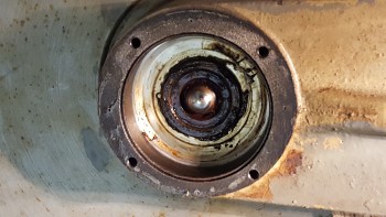
Platter and overhead
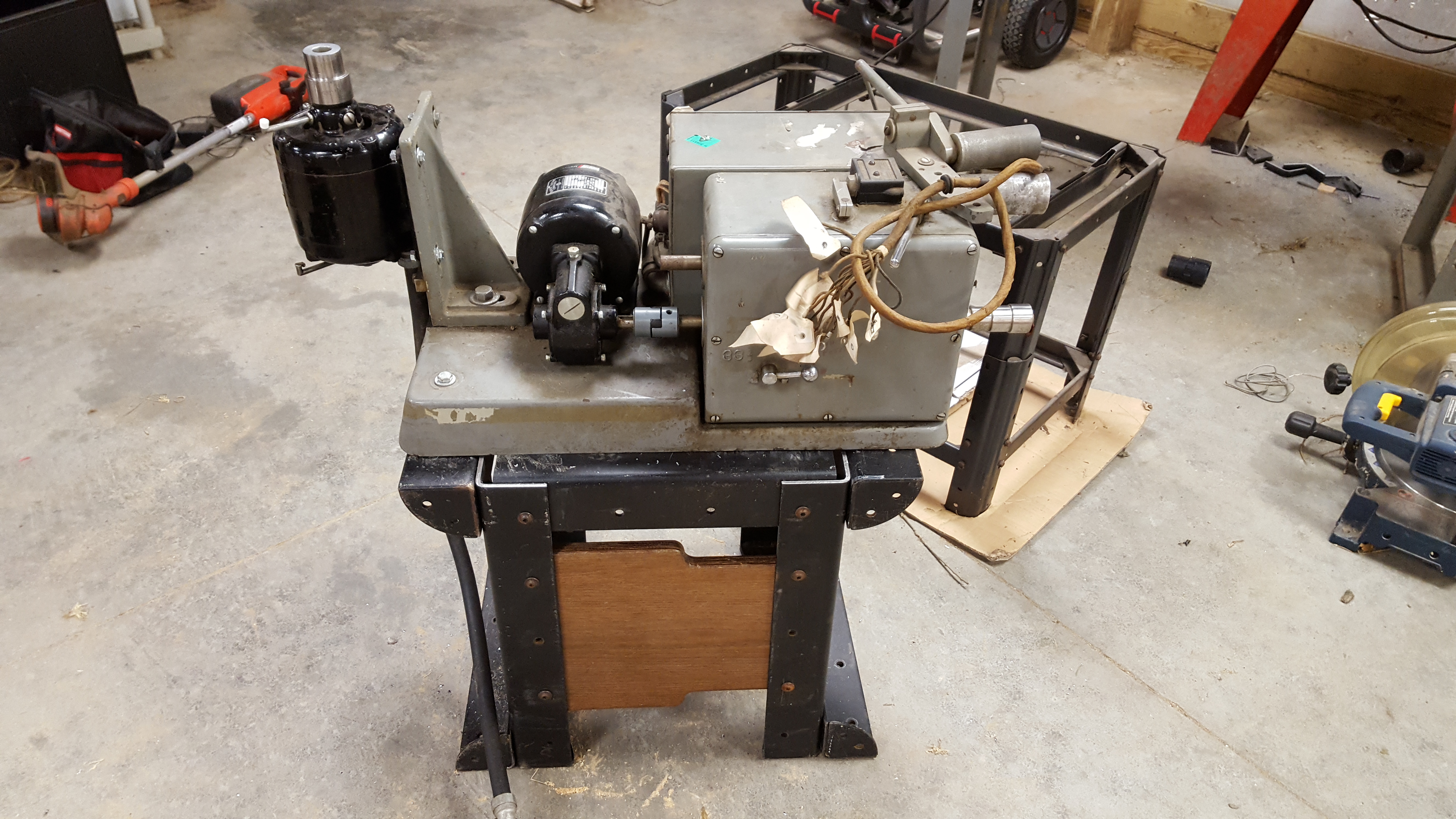
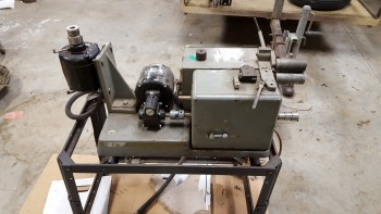
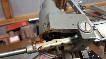
Image

Motors/gearbox
Image

Speed shifting on gearbox
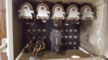
Image

Relays in gearbox
Image

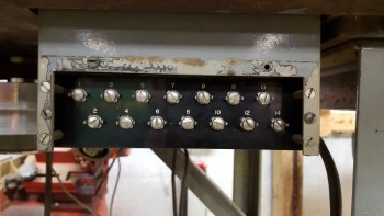
Relay connectors on lathe, connected to control buttons
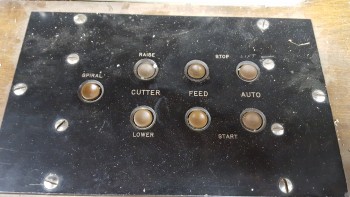
Image

Control buttons
Image

Underside - Pulleys
Image

Stepped pulley attached to feedscrew, mates to stepped pulley on gearbox
Image

Cutterhead lift mechanism, automated system
Image

Half-nut underneath sled
Image

Bare base
Image

Cutterhead manual lift/lower mechanism, tension spring
Image

Turntable Drive Motor
Image

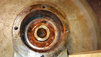
Underneath Platter - A.S.B 6.27.57 (the only date or resemblance to information on this lathe)
Image


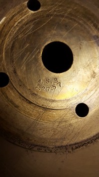
Quite an interesting beast. It uses a series of relays and micro switches to a automate the various processes. From what I can gather and others agree, it's a single LPI lathe that uses a gearbox with a stepped pulley off the gearbox and feedscrew to control the speed for in/out spirals as well as in-between track spirals. I don't see any sort of controls for changing the LPI itself. The platter motor has a pulley on the motor shaft that goes to a drive pulley that then is attached to the platter pulley. The platter itself is 50lbs of solid brass.

User avatar
rsimms3
Posts: 427
Joined: Thu Mar 14, 2013 10:01 am

Re: Mysterium Lathe - Restoration Project (Picture Heavy)

Post: # 40174Unread post rsimms3
Mon Feb 01, 2016 8:49 pm

Challenge #1 - Turntable Motor

The first challenge is having a motor to run this lathe. I don't have 208 - 3 phase hookup in my barn and really didn't want to have to install specialty power connectors. After a lot of research, discussion with my father and Bryan; I arrived at a combination Variable Frequency Drive and phase converter. Bryan (EpicenterBryan) had clued in on this when I was first reading around on the board here: http://lathetrolls.com/viewtopic.php?f=1&t=5217&p=31447&hilit=vfd#p31447 After some searching on eBay I found a drive to convert 1 phase to 3 phase, run 125v to 208v, and control the speed. I wanted speed control because by my rough calculations the pulleys on the motor and lathe wouldn't produce the correct speeds. These VFD drives, at least what I ended up with, are fantastic! If I had the funds to put one on my Presto 6D, I would do it in a heartbeat. Seems most of these are geared to industrial applications so single phase input/output aren't as common so they are a tad bit pricey. After wiring up the drive and adjusting the settings, I have full control in RPM or frequency to adjust the speed. Although I have some work to do on the pulleys (next post) I think this should work out fine once mounted properly.

User avatar
rsimms3
Posts: 427
Joined: Thu Mar 14, 2013 10:01 am

Re: Mysterium Lathe - Restoration Project (Picture Heavy)

Post: # 40175Unread post rsimms3
Mon Feb 01, 2016 8:58 pm

Challenge #2 - Pulley Maintenance

Next up was to check out how the pulleys were mounted. I lifted them slightly to remove the bottom covers to see what sort of bearing assembly was present. Both had a 1/2" ball bearing in the bottom with the platter pulley having a sealed bearing for centering. It was pretty nasty inside and the speed pulley was not properly lubricated as you can see below. I need to get this all cleaned up, re-lubricated, and reassembled. Then I can move the motor in place and start spinning the platter with the motor. Anyone have ideas on the rust colored goop? It was packed in the upper bearing and on the sides of the well, none on the single bearing itself.

Speed Pulley bearing, stuck in the shaft from hardened grease
Image

Bearing well
Image

Bearing itself (new one ordered)
Image

Platter Pulley
Image

Bearing well
Image

User avatar
sameal
Posts: 312
Joined: Sun May 24, 2015 10:13 pm
Location: Milwaukee, wi
Contact:

Re: Mysterium Lathe - Restoration Project (Picture Heavy)

Post: # 40178Unread post sameal
Mon Feb 01, 2016 9:19 pm

Looking good so far!

I still have nothing on this lathe digging around over here. Its like it just materialized there.

User avatar
dubcutter89
Posts: 359
Joined: Thu Oct 19, 2006 6:30 am
Location: between the grooves..

Re: Mysterium Lathe - Restoration Project (Picture Heavy)

Post: # 40192Unread post dubcutter89
Tue Feb 02, 2016 7:58 am

Nice machine and good progress!
VFD is the way to go - don't know why nobody else is doing this... but keep in mind that at reduced frequency you should also reduce voltage ie constant V/F (google v/f motor control...)

BTW, I found this pic somewhere on the net with somebody saying it was used by a big label...but who knows

Lukas
You do not have the required permissions to view the files attached to this post.
Wanted: ANYTHING ORTOFON related to cutting...thx

User avatar
rsimms3
Posts: 427
Joined: Thu Mar 14, 2013 10:01 am

Re: Mysterium Lathe - Restoration Project (Picture Heavy)

Post: # 40199Unread post rsimms3
Tue Feb 02, 2016 1:09 pm

Thank you!

I'll check out the frequency/voltage specs on my VFD, I believe with adjustment of the RPM or frequency it automatically adjusts the voltage, but I will confirm.

That picture looks pretty much spot on. Quick Google search of the picture gives me something to go off of in researching the history a little more. Now I'm intrigued.

User avatar
rsimms3
Posts: 427
Joined: Thu Mar 14, 2013 10:01 am

Re: Mysterium Lathe - Restoration Project (Picture Heavy)

Post: # 41373Unread post rsimms3
Tue Mar 15, 2016 10:52 pm

Milestone #1

With some days of warmth here in Michigan, I've been able to clean out the bearings for the pulleys, relubricate them, reassemble, and complete a brief test of the system under power. I need to source some new belts, but thankfully sameal was able to find the originals and send them to me. I have strobed the speed for the particular steps I was using this evening. Just seeing it spin was enough for today. I think the tapped holes in the base may have been for belt guides, they seem to wander quite a bit right now but then again who knows how old they are.

User avatar
recordboy
Posts: 243
Joined: Fri Oct 25, 2013 12:41 pm
Location: the 5th Dimension

Re: Mysterium Lathe - Restoration Project (Picture Heavy)

Post: # 41490Unread post recordboy
Sun Mar 20, 2016 8:59 pm

Congratulations...
Exciting progress...

cheers
Cheers,
recordboy

User avatar
rsimms3
Posts: 427
Joined: Thu Mar 14, 2013 10:01 am

Re: Mysterium Lathe - Restoration Project (Picture Heavy)

Post: # 43234Unread post rsimms3
Thu Jul 07, 2016 8:05 pm

Learning every day....

First, I bought some cheap angle iron and built a new stand (old one in the background, can be seen in previous pictures)
Image

Next I decided to buy a controller for the geared DC motor that was already mounted and came with the lathe. It has plenty of power with a speed of 43rpm. My original assumption was that the belt would slide up and down the stepped pulley for cutting spirals. What a ridiculous idea! It moves much to slowly for that. Instead, it has 4 different LPI based on the pulley system and the gearbox controls the spiral cut as I soon found out after attaching the controller. The gearbox has two speeds - 33.3 and 78 with matching spiral speeds. Below is video of the gearbox working and then pulling the spiral lever which looks like it was engaged possibly through a solenoid or some other mechanism I haven't quite figured out yet (I know it was automated because it's one of the marked control buttons on the control panel). I also have some gear noise. I know that the pulley shaft is bent, looks like it's bent into the gear casing causing a rub with every full rotation of the larger of the two gears.

Post Reply