thank you for all the info.
I just got a few more questions.
Do i use 2 separate wires one coming from the positive & the other coming from the negative? and then wrap the positive wire around the needle and the negative around the needle?
Or do i just use one wire connect it from the positive clip wrap it around the needle and then connect it to the negative clip?
sorry for all the questions!
I just wanna get this hooked up correctly so i can start cutting again.
Heating your cutting needle
Moderators: piaptk, tragwag, Steve E., Aussie0zborn

One wire. It is looped around the base of the sapphire. Then it is generally glued/epoxied into place.
Current runs through the wire from Positive to Negative of device that can vary current. So, there is typically a knob that allows you to make this selection and a meter that displays the current value.
The NiCr wire has a lot of resistance to current. Therefore, given the proper potential difference, the current will create heat within the wire. The heat is a product of the resistance of the wire and the forcing of the electrons through it.
Cutting, Inventing & Innovating
Groove Graphics, VMS Halfnuts, MIDI Automation, Professional Stereo Feedback Cutterheads, and Pesto 1-D Cutterhead Clones
Cutterhead Repair: Recoiling, Cleaning, Cloning of Screws, Dampers & More
http://mantra.audio
Groove Graphics, VMS Halfnuts, MIDI Automation, Professional Stereo Feedback Cutterheads, and Pesto 1-D Cutterhead Clones
Cutterhead Repair: Recoiling, Cleaning, Cloning of Screws, Dampers & More
http://mantra.audio

Our pleasure, I'm sure. Helps one comb his mind to think over these basics.Jccc wrote:thank you for all the info.
Jccc wrote:...Do i use 2 separate wires one coming from the positive & the other coming from the negative? and then wrap the positive wire around the needle and the negative around the needle?
Or do i just use one wire connect it from the positive clip wrap it around the needle and then connect it to the negative clip?
The second explanation you just gave is the correct one. As the Westrex manual explains, the wire is wrapped first around a no. 54 drill bit (as a coil-forming arbor). Then it is slid off the drill bit and slid onto the jewel.
Make sure that the selected length of wire conducts electricity when the potential is established at each end to be used.
- Ray Deyater
What cement is recommended. Mossy suggested dental cement. But there is a kind which requires a blue light for activation which may not be indicated, here. FortaFix?opcode66 wrote:One wire. It is looped around the base of the sapphire. Then it is generally glued/epoxied into place.
opcode66 wrote:Current runs through the wire from Positive to Negative of device that can vary current.
I hear you, Señor Tod, and what you're saying is technically true - but, permit me to add a burnishing facet of specificity to your broad strokes - a serif to your font of information. Just so our viewers know we are on the ball, here, let us say that current can be established through the wire. This means that electrons are moving very slowly from the negative potential to the positive. This is because there is no actual positive charge in valence shell orbit - only the absence of an electron or more, which renders the atom that much more "lean" of the particular negativity which renders the atom electrically neutral (with respect to the number of protons). A quaint term for this is "positivity." But, this is like describing the phenomenon called, "cold." There is in reality no such thing - only less thermal dynamism versus more of same. Relative to more warmth, there is more coldness, but only the amount of warmth (as in , degree of excitation - not "motional slumber") can be objectively measured...
The positron is a particle of anti-matter which annihilates an electron in a sudden null of quantum math. For "conventional," Franklinian Flow, positive-to-negative migration of charge carriers is achieved as the electron "holes" are moving from the positive terminal to the negative, like Spaghetti Western wagon wheel spokes moving in apparent reverse direction with the shuttering of the film against the strobing of the studio light mains AC...
It was Benjamin Franklin who made the first declaration about the polarity of current and he was actually incorrect. ): Now, it doesn't quite matter other than for academic interest. However, academic concerns are fascinating when they contradict conventional wisdom, imho.
Indeed, a varistor or rheostat can be fitted with a knob to allow the adjustment of the flow of charge carriers. I just read that the symbol for current, I, originates with the French term, L'intensité du courant électrique. Intense!opcode66 wrote: So, there is typically a knob that allows you to make this selection and a meter that displays the current value.
Also, I read an interesting blog once which explained that current does not quite "flow." The reason is that current is flow. One doesn't usually say that the flow flows. Therefore, one simply needs to say that there is or is not any current. Chouette.
opcode66 wrote: The NiCr wire has a lot of resistance to current.
Quite - for a wire. For a resistor, it is only abou 32 Ohms per foot, according to the Westrex spec. One doesn't expect much of a voltage drop from a wire, but NiChrome has far more admittance than, say, an aqueous solution of Copper Sulfamate.
The electrons are forced through very slowly - maybe 1 mm/sec? But the flow of charge, from the Domino-effect propagation wave, is much closer to "C," which is the exciting factor leading to the power dissipation known as electrical heat. "Burnin' up them panneez." Just a different way to "lens" it.opcode66 wrote: Therefore, given the proper potential difference, the current will create heat within the wire. The heat is a product of the resistance of the wire and the forcing of the electrons through it.
- So many dynamos
Hello everyone and thanks for all the information. I finally got the heater hooked up and touched the stylus and felt some heat. I did a few test cuts on some picnic plates and noticed a big difference in how much it took away some noise.
Now i have another problem.
It seems the swarf is sticking to the stylus! Is there anyway to prevent it from melting to the needle?
Before i didnt have the heater i would just brush away the chip but now its starting to melt to it.
Im lucky i wa testing this out with a old needle.
Now i have another problem.
It seems the swarf is sticking to the stylus! Is there anyway to prevent it from melting to the needle?
Before i didnt have the heater i would just brush away the chip but now its starting to melt to it.
Im lucky i wa testing this out with a old needle.
This is not good. When chip melts onto the stylus it carbonizes and essentially bonds at a molecular level. Acetone will not remove carbonized chip from your stylus. It is "baked" as they used to say. So, yes, it is good that you were working with a less than perfect stylus to begin with.
I think you need to back off on the current a bit. Too much heat causes the scenario you are describing.
On a Neumann setup 0.5 Amps at 12 Volts is applied to the heating wire. However, Neumann lathes have a vacuum system to remove chip. The suction serves a dual purpose of also cooling the stylus slightly.
So, on a system with suction to remove chip, 0.5 Amps at 12 Volts should be perfect. Without suction, you need to back off on the current. A simple circuit with power supply, an ammeter that reads 0 to 1 or 2 amps and a potentiometer allows you to fine tune the current and thereby the temperature to your particular needs. Without a vacuum suction system I would suggest less than 0.5 Amps at 12 Volts.
Cutting, Inventing & Innovating
Groove Graphics, VMS Halfnuts, MIDI Automation, Professional Stereo Feedback Cutterheads, and Pesto 1-D Cutterhead Clones
Cutterhead Repair: Recoiling, Cleaning, Cloning of Screws, Dampers & More
http://mantra.audio
Groove Graphics, VMS Halfnuts, MIDI Automation, Professional Stereo Feedback Cutterheads, and Pesto 1-D Cutterhead Clones
Cutterhead Repair: Recoiling, Cleaning, Cloning of Screws, Dampers & More
http://mantra.audio
Mahalo, Jccc,opcode66 wrote:This is not good. ...Without a vacuum suction system I would suggest less than 0.5 Amps at 12 Volts.
I and my partners agree with Opcode66. Paul Gold warned me about the importance of chip removal with heated stylus cuts, which I think he said is wise to cancel at the first sign of chip removal not being perfect. Picnick plate string is not as flammable as nitrocellulose lacquer, but, the idea of not fouling the groove and keeping the stylus clean is probably Universally applicable (see below)... I should therefore go so far as to discourage hot stylus cuts unless vacuum chip removal is implemented.
On the cover of Disk Recording 1930-1960, by R. K. Morrison, you can see that each of these old Universal lathes at Pictosound had vacuum chip removal, even though it was a long time ago, and the turntables were primitively belt-driven, doing only lateral cuts at fixed pitch. So, suction of debris from the workpiece is a basic part of the cutting system. It's even used by part-making lathes. In fact, the AES Anthology describes hot stylus cutting as a two-fisted process involving both scrape-engraving and suction of that which is being scraped away (as it is being scraped away - push/pull).
The nozzle is the hard part. But the gist, which was learned by us from MossBoss and Island Audio Engineering, is that the nozzle should be about 1/2" or less from the stylus and be riding only between ~1/16" and ~1/32" above the blank. Riding this close to the surface, and rather parallel to it, means that a tube must be flattened to the extreme ovular habit. This maintains the flow, increases the velocity (Bernoulli), and maximizes the sweep (width of "grabbing" area). It should also be most likely right in front of the action (for least carbonization of the jewel).
You know you are not at the right nozzle height if when moving the carriage over the turntable there is no change in the sound of the suction. Here, there is heard a change in the sound as soon as the nozzle passes over the turntable and then another change in sound as it gets closer to the surface below when it passes over the blank. 3 different pitches of hiss before you start tuning stylus heat... No skimping. These details were mapped out by the sacred elders of a gentle race... Or not. );
Brush removal is far better for cold cuts. If heat is making the difference with your plates, until you get a vacuum tube with nozzle developed, for brushing swarf, I'd recommend using a low hanging heat lamp and heating the blank rather than the stylus. Based on the available coffee table books, that is a time-honored method.
Also, to echo what Opcode66 says, less heat on the jewel is better than more. The heat is tuned to be that which is the least that makes the noise drop to the acceptably low level. The heat will increase as a long side is cut, so one might wish to slim down the (heater) current during the recording.
Get two volume pedal pots. Use one wah-wah for stylus heat; the other, for depth of cut. Right hand on the dial for LPI, and left hand on the focus of the microscope. (Chip nozzle is attached to carriage (and so, automagically moves with the stylus at which the nozzle entrance is aimed), and this rigid nozzle mates with a flexible surgical hose for unimpeded swarf-to-jar vacuum filtration); Simple.
Ooga-Booga brand lathes, you do the welding (?"
- M. Broyle
Re: Heating your cutting needle
When applying heat to the stylus on our machine, we also run the vacuum system simultaneously, so as not to allow overheating of the stylus. I have seen at least one stylus damaged from excessive heat.
We use a double pole switch that engages both the heater circuit and the vacuum system when switched "on". With a new stylus, we run about 400 mA into the heater wire; as the stylus ages we crank it up nominally, but after awhile the wear on the stylus tip wins out, and we need to swap in a new needle.
We use a double pole switch that engages both the heater circuit and the vacuum system when switched "on". With a new stylus, we run about 400 mA into the heater wire; as the stylus ages we crank it up nominally, but after awhile the wear on the stylus tip wins out, and we need to swap in a new needle.
Re: Heating your cutting needle
I've always wanted to install a transistor in my lathe to keep the stylus heat current from flowing if the vacuum is not on. Someday I'll do that....
Cutting, Inventing & Innovating
Groove Graphics, VMS Halfnuts, MIDI Automation, Professional Stereo Feedback Cutterheads, and Pesto 1-D Cutterhead Clones
Cutterhead Repair: Recoiling, Cleaning, Cloning of Screws, Dampers & More
http://mantra.audio
Groove Graphics, VMS Halfnuts, MIDI Automation, Professional Stereo Feedback Cutterheads, and Pesto 1-D Cutterhead Clones
Cutterhead Repair: Recoiling, Cleaning, Cloning of Screws, Dampers & More
http://mantra.audio

Re: Heating your cutting needle
I do think that all has been said about the issue of stylus heat more than once
I cannot help but observe the fact that recently we have almost a re run of questions which have been covered in the past
I will add this rather old way of dealing with chip removal rather than add to the existing (repeated) thread it may be useful to some here using certain machines, it is not applicable to all the gear used out there
An old well used method in day's gone past was to get hold of the chip from the front of the stylus with a pointy camel hair brush and give it a quick wrap around the center spindle, assuming it is accessible of course as it is in some cutting machines
(I reserve the name lathes for pro gear)
It will wind the chip around the spindle as it spins providing an anchor point for it, It will not take all of it up of course due to the difference in the length being cut, as the outside peripheral length is much greater in reference to that of the spindle,
However one can pick the issuing chip more than once, keep on wrapping it around the spindle
Let it spin for a little while longer after the end of the cut
One will than have a little ball of the chip neatly wound around the spindle which comes off when you remove whatever you cut on
A bit of very thin double sided sticky tape wrapped around the spindle makes the job much easier, but it also makes it a bit harder to remove later, no big deal a bit more care is required
The chip will have to be continuous which is a must regardless however since some guys here use all kinds of media to cut on a broken chip is much easier dealt with as described above
Cheers
Chris
Re: Heating your cutting needle
All's you need is a microswitch that is switched by the movement of the head drop. (The green and white jacketed wires go to the microswitch for stylus heat current that is powered when the head drop causes the metal on the back to lift off the switch. It's a switch that breaks when pushed down and makes when lifted off of...)opcode66 wrote:I've always wanted to install a transistor in my lathe to keep the stylus heat current from flowing if the vacuum is not on. Someday I'll do that....

- Serif

Re: Heating your cutting needle
this works well for me on the Presto, especially because I'm not cutting lacquers for pressing.mossboss wrote: An old well used method in day's gone past was to get hold of the chip from the front of the stylus with a pointy camel hair brush and give it a quick wrap around the center spindle, assuming it is accessible of course as it is in some cutting machines
I have cut picnic plates and laser discs with pretty consistent results.
making lathe cuts on a Presto 6N, HIFI stereo cuts on vinylrecorder
at Audio Geography Studios, Providence, RI USA
http://www.audiogeography.com
at Audio Geography Studios, Providence, RI USA
http://www.audiogeography.com
-
Greg Reierson

- Posts: 198
- Joined: Thu Jul 29, 2010 1:31 pm
- Location: Minneapolis, MN
- Contact:
Re:
Len Horowitz says good ol' fashioned white wood glue will work fine. Anyone ever tried it?Serif wrote:What cement is recommended. Mossy suggested dental cement. But there is a kind which requires a blue light for activation which may not be indicated, here.
-
yourbedhead

- Posts: 69
- Joined: Sat Apr 23, 2016 6:00 pm
- Location: Fort Worth, Texas
- Contact:
Re: Heating your cutting needle
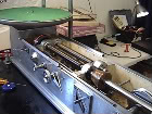
Can someone show a picture of their setup so I have a visual to go along with this? I am having a hard time grasping how to accomplish this. thanks
-
yourbedhead
- Posts: 69
- Joined: Sat Apr 23, 2016 6:00 pm
- Location: Fort Worth, Texas
- Contact:
Re: Heating your cutting needle
Is there nothing out there showing how to do this? A schematic?
-
yourbedhead
- Posts: 69
- Joined: Sat Apr 23, 2016 6:00 pm
- Location: Fort Worth, Texas
- Contact:
Re: Heating your cutting needle
Here is one pdf I found...
yourbedhead wrote:Is there nothing out there showing how to do this? A schematic?
You do not have the required permissions to view the files attached to this post.
-
yourbedhead
- Posts: 69
- Joined: Sat Apr 23, 2016 6:00 pm
- Location: Fort Worth, Texas
- Contact:
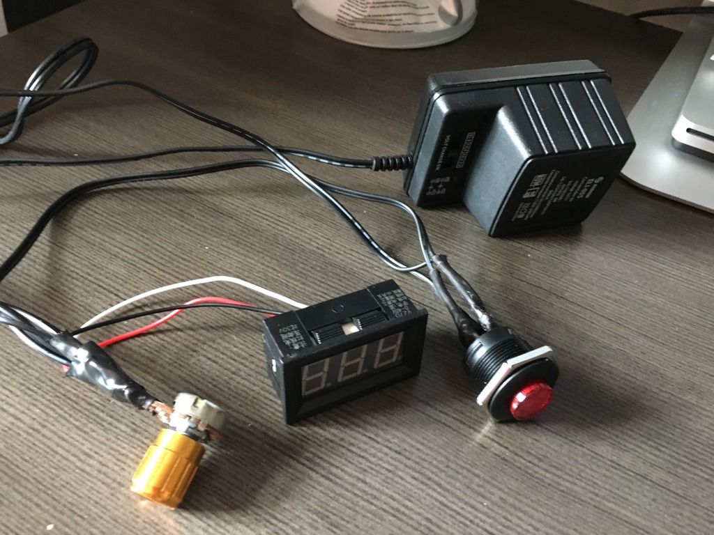
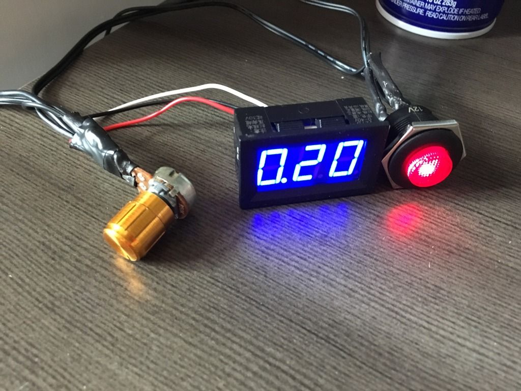
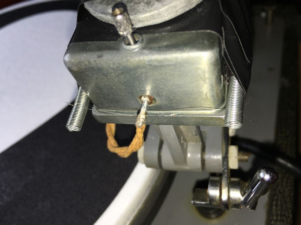
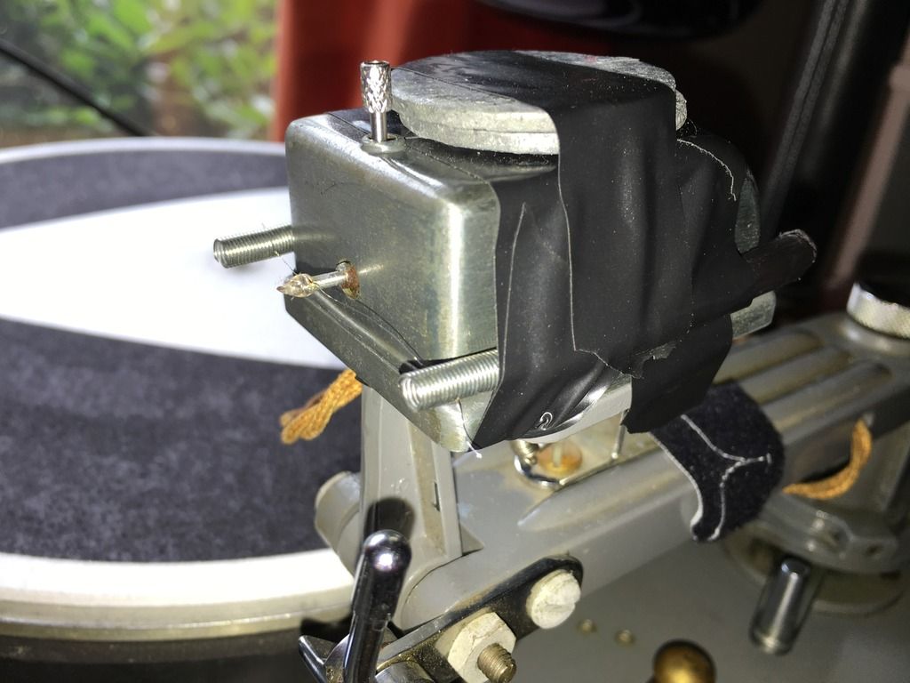
Re: Heating your cutting needle
Here are pics of my setup too... I plan on connecting to a box or board at some point...