Question, for those who own, or are very familiar with, Neumann and/or Scully lathes, about the "sled" transport mechanics: (the chunk of metal that carries the cutterhead towards the turntable)
Does anyone have photos they'd like to share, or diagrams they can draw from memory, of how the Neumann and/or Scully lathe sled transports are constructed?
The only lathe transports I've seen have been the overhead Presto/Rek-O-Kut kind - a couple of steel linear slidebars with a feedscrew. Obviously, if you're interested in high quality lathe construction, that will only take you so far. Maybe some ball bearings here, some oil damping there, some rubber acoustic isolation pads... you could get "creative & experimental", but I'm really curious how The Bosses chose to do it, with the culmination of all their years of research. And I don't know any locals with a Scully or Neumann well enough to ask them to open it up.
Thanks,
- Bob
-
blacknwhite

- Posts: 483
- Joined: Thu Apr 24, 2008 2:57 am
- Location: US

I don't have pictures of any of this, but I have used and can remember how the cutter traversed over the lathe bed on some of the Neumann and Scully models. On the Neumann AM-32b (and on the VMS-70, if I remember right) the upper carriage structure rolled on ball bearings over two long flat, ground surfaces on the bed. The leadscrew ran between these surfaces and the half-nut was dropped onto it by the operator via a lever system to engage the feed. I don't recall any rubber dampers being used. There was a dust shield over the mechanism to keep dirt away from the area as obviously these surfaces must be kept clean. On the old Scully (can't remember the model number, but it was an early one without automatic pitch control), the "ways" on the bed were "V" shaped, pointed upward. The lathe carriage rolled on grooved rollers which sat on the V ways. Again, the leadscrews (this model had two - one for inward drive and one for outward) ran between the V ways. The ways and rollers were fully exposed, so they needed to be cleaned frequently. I don't recall there being any rubber dampers used in this carriage support system.
Collecting moss, phonos, and radios in the mountains of WNC

The Scully system is similar to the Neumann, but the sled rides on 3 points of contact, one with a 'V' shaped pulley that sits over a corresponding track on the front of the lathe, the rear (directly behind) is a ball-bearing wheel that rides on a ground track, and the third point is a precision ground 'V' shaped blade that rides in a grooved pulley at the right end of the machine. The feedscrews are under the carriage and are engaged in a similar manner to the Neumann - one for inside-out and the other for outside-in.
-
blacknwhite
- Posts: 483
- Joined: Thu Apr 24, 2008 2:57 am
- Location: US
Here's the image I'm getting, at least for the Scully: And for the Neumann, just have a ball bearing both in front and back, rather than a grooved wheel in front:

It's my understanding that the ball bearing is not attached to either the base or the sled. But this raises the question: If the ball bearing is totally free, then is it a common problem for the ball bearing to somehow "creep", over time, too far to the left or right? One possible example of the problem:

I guess if that IS the case, it would require the owner to periodically lift and move the sled all the way to the right, while also rolling the ball all the way to the right - sort of a re-calibration procedure...
Again, for the Neumann, the picture I get is that it would just be three ball bearings, instead of one ball bearing and two grooved pulleys.
Does this "generally look right" for the principles of the Neumann & Scully transports, or is something really basic missing/wrong?
Another general question: What's the "bathtub" I've heard mentioned?
Thanks,
- Bob
It's my understanding that the ball bearing is not attached to either the base or the sled. But this raises the question: If the ball bearing is totally free, then is it a common problem for the ball bearing to somehow "creep", over time, too far to the left or right? One possible example of the problem:
I guess if that IS the case, it would require the owner to periodically lift and move the sled all the way to the right, while also rolling the ball all the way to the right - sort of a re-calibration procedure...
Again, for the Neumann, the picture I get is that it would just be three ball bearings, instead of one ball bearing and two grooved pulleys.
Does this "generally look right" for the principles of the Neumann & Scully transports, or is something really basic missing/wrong?
Another general question: What's the "bathtub" I've heard mentioned?
Thanks,
- Bob
Last edited by blacknwhite on Tue Jan 20, 2009 6:51 pm, edited 1 time in total.
B&W, your first picture is essentially correct at its right side. I should have been more careful in my description. There is no large, loose ball roller. The sled or carriage on the Scully is suspended on conventional ball bearings (rather than sleeves or bushings) inside of V-shaped rollers or wheels such as you have shown on the right side of your picture. The Scully has three such V-shaped rails, one fore and one aft toward the platter with the leadscrew sitting between them and one rail only at the outside or tail part of the carriage. This provides 3-point suspension which simplifies the leveling and alignment of the lathe bed without any rocking or tottering of the carriage. Since the ball bearings are within the wheels and the wheels are on V rails (i.e. the carriage is a 3 wheel roller skate on rails), there are no loose balls that need adjustment.
The Neumann is the same basic idea, but the rails are not V shaped but flat. I can't remember if it is a 3 or a 4 wheel suspension, and I don't remember how the carriage is retained from sliding off the rails since they are not V shaped. I think the carriage is retained by sliding guides in a manner more similar to the carriage arrangement of a metal turning lathe. It's not obvious how the carriage is guided because all the wheels and guides are covered by protective plates and covers. I never bothered to remove the plates to have a look.
The Neumann is the same basic idea, but the rails are not V shaped but flat. I can't remember if it is a 3 or a 4 wheel suspension, and I don't remember how the carriage is retained from sliding off the rails since they are not V shaped. I think the carriage is retained by sliding guides in a manner more similar to the carriage arrangement of a metal turning lathe. It's not obvious how the carriage is guided because all the wheels and guides are covered by protective plates and covers. I never bothered to remove the plates to have a look.
Collecting moss, phonos, and radios in the mountains of WNC
-
blacknwhite
- Posts: 483
- Joined: Thu Apr 24, 2008 2:57 am
- Location: US
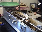
I'm refurbishing a Scully lathe with Westrex head & electronics this week, and will be putting up photos and videos shortly. Here's a photo of the lathe with the cutting head carriage removed, exposing the rails and rear trolley support wheel, and showing the forward and reverse feed screws. As you can see, it's significantly different than the Neumann design:

Here's a link to some photos of said lathe: http://s1150.photobucket.com/albums/o615/audadvnc/Scully_Lathe/?albumview=slideshow
Here's a link to some photos of said lathe: http://s1150.photobucket.com/albums/o615/audadvnc/Scully_Lathe/?albumview=slideshow
Last edited by audadvnc on Wed Feb 08, 2012 9:16 pm, edited 12 times in total.
-
concretecowboy71

- Posts: 569
- Joined: Mon Mar 08, 2010 10:13 am
- Location: Cleveland, Ohio, USA
- Contact:
https://lathetrolls.com/viewtopic.php?t=2323&highlight=&mforum=lathetrolls
These are pictures I posted last year of a disassembled Neumann carriage.
They will show some things like the bed, the dovetails and the location of the bearing the sits inside the bed at the end of the lead screw.
These are pictures I posted last year of a disassembled Neumann carriage.
They will show some things like the bed, the dovetails and the location of the bearing the sits inside the bed at the end of the lead screw.
Cutting Masters in Bristol,Virginia, USA
Well Made Music / Gotta Groove Records
Well Made Music / Gotta Groove Records

I trust it this is a Scully 501 model, based on the gearbox - which I recognized immediately as the kind of pitches used by Columbia's New York studios throughout the '50's on their 45's and some LP's, up to summer 1966. I see in the closeup of the gearbox (having seen the pics in that Photobucket link), below the 88-136 lpi pitches, a secondary group of pitches of 150, 164, 178, 192, 206, 220 and 234 lpi (increased in increments of 14 lpi) - most of which were also used by Columbia mastering engineers. And since their Scully also cut at 1.5 times the aforementioned pitches, the advance in gearbox pitch came as follows:audadvnc wrote:I'm refurbishing a Scully lathe with Westrex head & electronics this week, and will be putting up photos and videos shortly. Here's a photo of the lathe with the cutting head carriage removed, exposing the rails and rear trolley support wheel, and showing the forward and reverse feed screws. As you can see, it's significantly different than the Neumann design:
Here's a link to some photos of said lathe: http://s1150.photobucket.com/albums/o615/audadvnc/Scully_Lathe/?albumview=slideshow
a. 132, 144, 156, 168, 180, 192 and 204 lpi
b. 225, 246, 267, 288, 309, 330 and 351 lpi
Of the higher pitches, the last two cited in each variant (220 and 234 lpi, and 330 and 351 lpi) were, to my knowledge, not used by Columbia's mastering engineers of the time, and I only saw the 178 lpi pitch on an LP mastered in the early '60's.
Besides the 150-234 lpi secondary gearbox pitch, another set of pitches (as on the Scully 501 in use at Paul Brekus' Aardvark Mastering in Colorado - a lathe previously in use at two Nashville studios, Hilltop and before that Columbia) besides 88-136 were:
178, 194, 210, 226, 242, 258 and 274 lpi
which I seemed to notice on some USA Decca 45's (namely the original release of "We're Not Gonna Take It" by The Who in 1969 as b/w "I'm Free").

blacknwhite wrote:Here's the image I'm getting, at least for the Scully: And for the Neumann, just have a ball bearing both in front and back, rather than a grooved wheel in front:
...
I like the way that Scully, in true builder fashion, rejected the "capstone" of the bedway vee. The tops of the pyramidal vee ways (and trolley wheel rims) are actually lopped off, flat, unlike in the drawing.
However, this mesa habit is apparent in the photograph that was shared.
http://s1150.beta.photobucket.com/user/audadvnc/media/Scully_Lathe/IMG_6087.jpg.html?sort=6&o=33
- Andrew
Here's a link to a blog which includes photos on the Scully bedways.
http://home.fuse.net/injanius/LS-76_B_14.html
- Andrew
http://home.fuse.net/injanius/LS-76_B_14.html
- Andrew